AAMToolbox template: Difference between revisions
Jump to navigation
Jump to search
No edit summary |
No edit summary |
||
| (8 intermediate revisions by the same user not shown) | |||
| Line 1: | Line 1: | ||
[[Tutorials on the Shape modelling toolbox#1|Back to Tutorial pages]]<br> | [[Tutorials on the Shape modelling toolbox#1|Back to Tutorial pages]]<br> | ||
=Template Editor= | =Template Editor= | ||
== | ==1) Start a new project from the AAMToolbox control panel== | ||
{| border=" | [[AAMToolbox new project|Tutorial on starting a new project]]<br> | ||
|- valign="top" | Notice that one of the images copied into the project has been co-opted as an icon representing the project. <br> | ||
|width="300px"| | [[File:AAMToolbox_GUI2.png|500px|The AAMToolbox control panel after adding the image files]]<br> | ||
[[File: | Once the template has been added, a second icon will be automatically created that represents the template itself. | ||
==2) Select an image on which to base the template== | |||
{| border="0" cellpadding="5" cellspacing="5" | |||
|- valign="top" | |||
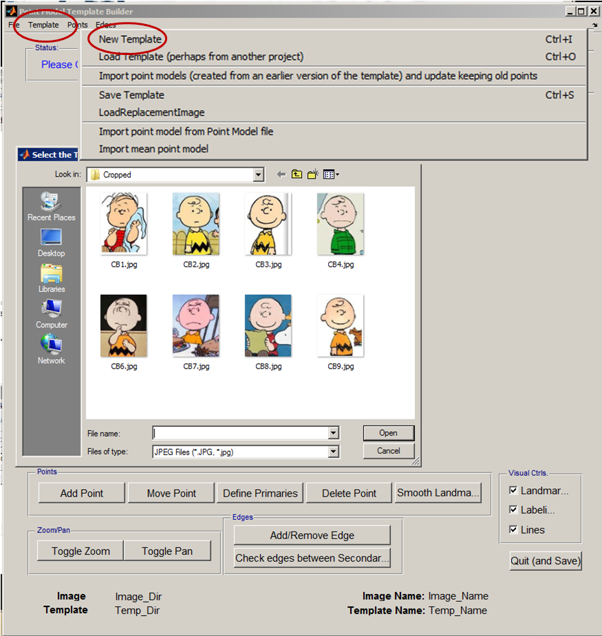
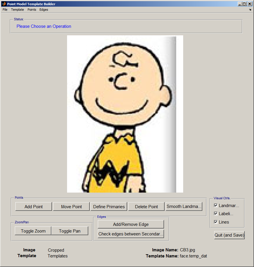
|width="300px"| Select the '''Template Editor from the AAMToolbox control panel'''. Then, from the Template Editor menu select''' New Template'''. This will open the directory of Cropped images and allow you to select one on which to base the template. [[File:AAMToolbox_Selecting_Template_Image.png|400px|Point model template builder interface]] | |||
<small>Idea: From the Templates menu, Templates (and associated images) can be copied from other, existing, projects. ''</small> | |||
|width="300px"|[[File:AAMToolbox_new_template.png|300px|Point model template builder interface]]<br> | |||
'' | The''' new template''' will be based on this image. | ||
|width=" | |||
The | |||
|} | |} | ||
==Template Editor | ==3) Create a new Template using the Template Editor== | ||
{| border=" | {| border="0" cellpadding="5" cellspacing="5" | ||
|- valign="top" | |- valign="top" | ||
|width="300px"| | |width="300px"| | ||
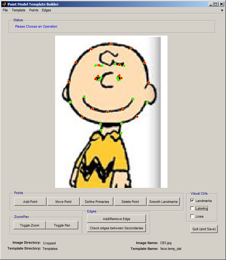
|width=" | #Add points, '''select 'Add Point'''' and click on a feature that can be recognised in every image. For example, the junction between face and neck, or face and ear lobe, the ends. | ||
#Having added the points, define those that you are most reliable as 'primary'. They will turn green. The remaining points are called secondary points and should be spread evenly between primary points. | |||
#Secondary points can be''' spread evenly''' along a cubic spline that joints the primary landmarks by selecting 'Smooth Landmarks'. | |||
#Lines joining points can aid understanding, but they do not contribute to the final shape model. <br> | |||
When the template is correct 'Quit (and Save)' using the button, bottom right.<br> | |||
|width="300px"|[[File:Template2.jpg|300px|Point model template builder interface]]<br> | |||
#The''' point model is a set of points''' (red and green dots) that are used to build the shape model | |||
#These are subdivided into primary (red) and secondary (green) landmarks | |||
#Edges (red lines) are added to make the point model more understandable to humans | |||
|} | |} | ||
==4) Choose a template using the AAMToolbox control panel== | |||
'''Having created a template it should be selected''' using the AAMToolbox main interface, 'Choose Template'. <br> | |||
[[File:Choose_Template_AAMToolbox.png|500px|The AAMToolbox control panel after adding the image files]]<br> | |||
Once the template has been added, a second icon will be automatically created that represents the template itself. Here it is the red smiling face.<BR> | |||
Notice: | |||
#The name of the current working project, top left | |||
#The template name together with the number of points | |||
#The current set of points (that will be selected automatically) | |||
#The current list of images (that will be selected automatically) | |||
#Most importantly, these details are summarised in the Listbox. Each model that is created will be associated with an entry in this listbox. | |||
#The next step is to move the point model into position over each of the images using the '''Point Model Editor'''. | |||
Latest revision as of 17:00, 5 February 2012
Template Editor
1) Start a new project from the AAMToolbox control panel
Tutorial on starting a new project
Notice that one of the images copied into the project has been co-opted as an icon representing the project.
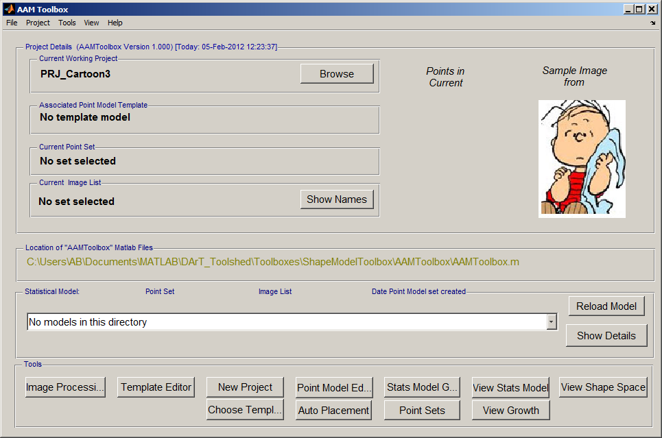
Once the template has been added, a second icon will be automatically created that represents the template itself.
2) Select an image on which to base the template
3) Create a new Template using the Template Editor
4) Choose a template using the AAMToolbox control panel
Having created a template it should be selected using the AAMToolbox main interface, 'Choose Template'.
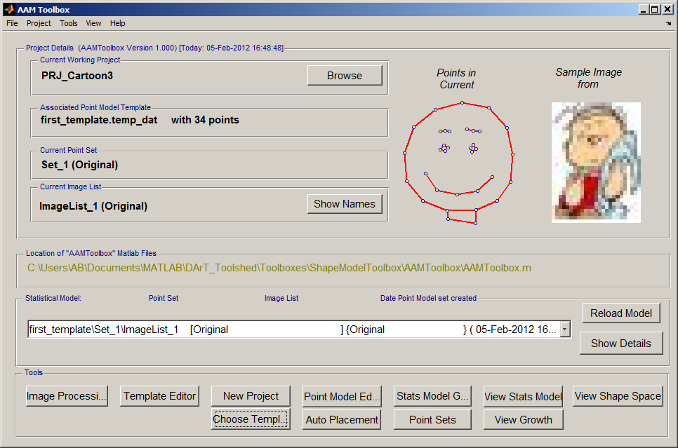
Once the template has been added, a second icon will be automatically created that represents the template itself. Here it is the red smiling face.
Notice:
- The name of the current working project, top left
- The template name together with the number of points
- The current set of points (that will be selected automatically)
- The current list of images (that will be selected automatically)
- Most importantly, these details are summarised in the Listbox. Each model that is created will be associated with an entry in this listbox.
- The next step is to move the point model into position over each of the images using the Point Model Editor.
